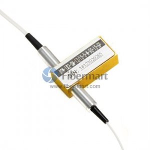
1×2 Opto-Mechanical Optical Switches
FM SKU#:SKU60431J
Model#:OSW-1×2
MFG PART#:
Model#:OSW-1×2
MFG PART#:
1×2 Opto-Mechanical Optical Switches
The 1×2 Opto-Mechanical Bi-directional Fiber Optic Switch connects optical channels by redirecting 1 incoming optical signals into 2 output fibers. This is achieved using a opto-mechanical configuration and activated via an electrical control signal. The switch has integrated electrical position sensors.Based on thin film filter technology that provides a robust method of altering the light patch, this series of products has a drastically simplified platform configuration offering high reliability and low production cost. This novel design significantly reduces moving part position sensitivity, offering unprecedented high stability as well as an unmatched low cost.
Fiber-Mart offers most affordable high performance Opto-Mechanical Fiber Optic Switches. Our Mechanical Fiber Optic Switches are tested in-house prior to shipment to guarantee that they will arrive in perfect physical and working condition. Currently configurations includes 1×1, 1×2, 1×4, 1×8, 2×2, 2x2A, 2x2B, and 2x2BA as well as Dual 2×2 and Dual 2×2 Bypass configurations for single mode or multimode fibers. For more information about Opto-mechanical fiber optic switches, please e-email sales@fiber-mart.com.
Fiber-Mart offers most affordable high performance Opto-Mechanical Fiber Optic Switches. Our Mechanical Fiber Optic Switches are tested in-house prior to shipment to guarantee that they will arrive in perfect physical and working condition. Currently configurations includes 1×1, 1×2, 1×4, 1×8, 2×2, 2x2A, 2x2B, and 2x2BA as well as Dual 2×2 and Dual 2×2 Bypass configurations for single mode or multimode fibers. For more information about Opto-mechanical fiber optic switches, please e-email sales@fiber-mart.com.
Features
|
Applications
|
Specifications
| Parameters | Multimode | Singlemode | Unit |
| Wavelength Range | 650 ~ 1310 | 1260 ~ 1670 | nm |
| Testing Wavelength | 650/780/850/980/1064/1310 | 1310/1490/1550/1625/1650 | nm |
| Insertion Loss | Typ: 0.6, Max: 1.0 | Typ: 0.5, Max: 0.8 | dB |
| Return Loss | ≥ 30 | ≥ 50 | dB |
| Crosstalk | ≥ 35 | ≥ 55 | dB |
| PDL | ≤ 0.05 | dB | |
| WDL | ≤ 0.25 | dB | |
| TDL | ≤ 0.25 | dB | |
| Repeatability | ≤ ±0.02 | dB | |
| Power supply | 3.0 or 5.0 | v | |
| Lifetime | ≥ 107 | Cycle | |
| Switch Time | ≤ 8 | ms | |
| Transmission Power | ≤ 500 | mW | |
| Operation Temperature | -40 ~ +85 | ℃ | |
| Storage Temperature | -40 ~ +85 | ℃ | |
| Weight | 16 | g | |
| Dimension | (L)27 x (W)12.6 x (H)8.5(±0.2) | mm |
Note:
1. All parameters are for device without connectors.
2.Special specifications can be customized according to customer requirements.
1. All parameters are for device without connectors.
2.Special specifications can be customized according to customer requirements.
Optical Route

Mechanical Dimensions (Unit: mm)
.jpg)
Electrical Driving Requirements
The load is a resistive coil which is activated by applying 5V (draw ~ 40mA). Applying too long pulse for the latching version will heat up the device. Fiber-Mart also offers TTL, USB, and RS232 interfaces as an option-please contact Fiber-Mart sales at service@fiber-mart.com.
| Optical Path | Electric Drive | Sensor Status | |||||
| 1×2 | 1 | 5 | 6 | 10 | 3-4,7-8 | 2-3,8-9 | |
| Latching | P1—P2 | +5V | GND | N/A | N/A | CLOSE | OPEN |
| P1—P3 | N/A | N/A | GND | +5V | OPEN | CLOSE | |
| Non- Latching | P1—P2 | N/A | N/A | N/A | N/A | CLOSE | OPEN |
| P1—P3 | N/A | GND | +5V | N/A | OPEN | CLOSE |
Functional Diagram
| Specification | Voltage | Current | Resistor |
| 5V Latching | 4.5~5.5 | 36~44mA | 125Ω |
| 5V Non-Latching | 4.5~5.5 | 26~32mA | 175Ω |
| 3V Latching | 2.7~3.3 | 54~66mA | 50Ω |
| 3V Non-Latching | 2.7~3.3 | 39~47mA | 70Ω |
Order information: OSW-1×2-A-B-C-D-E-F-G
Fiber-Mart provides customized design optical switches to meet special control and applications. Also, Fiber-Mart offers modular assemblies that integrate other components to form a full function modules or subsystem. For details, please contact Fiber-Mart at support@fiber-mart.com.
Question:
1. Number of switching ports: 1, 2, 3, 4, 8, or 12.
2. What wavelengths are you using?
3. Which core/cladding size are you using?
4. What type of connectors do you need?
5. How long should the fibers be? What size jacketing?
6. Are there any other special requirements?
Question:
1. Number of switching ports: 1, 2, 3, 4, 8, or 12.
2. What wavelengths are you using?
3. Which core/cladding size are you using?
4. What type of connectors do you need?
5. How long should the fibers be? What size jacketing?
6. Are there any other special requirements?
| A | B | C | D | E | F | G |
| Mode | Wavelength | Voltage | Control Model | Fiber Diameter | Fiber Length | Connector |
| SM: 9/125um | 85: 850nm | 3: 3V | L: Latching | 25: 250um | 05: 0.5m | OO: None |
| M5: 50/125um | 13: 1310nm | 5: 5V | N: Non-Latching | 90: 900um | 10: 1.0m | FP: FC/PC |
| M6: 62.5/125um | 14: 1490nm | S: Special | S: Special | 20: 2.0mm | 15: 1.5m | FA: FC/APC |
| S: Special | 15: 1550nm | 30: 3.0mm | S: Special | SP: SC/PC | ||
| 162: 1625nm | S: Special | SA: SC/APC | ||||
| 165: 1650nm | LP: LC/PC | |||||
| 13/15: 1310/1550nm | LA: LC/APC | |||||
| S: Special | S: Special |
For example: OSW-1×2-M6-13-5-L-S-15-FP

