1m LC to LC OM1 Mode Conditioning Fiber Optic Patch Cable
Fiber-MART manufactures and supplies standard and custom length 50/125,62.5/125 and OEM equivalent mode conditioning fiber optic patch cords for 1000BASE-LX/LH Gigabit Ethernet(1300nm long wavelength)applications installed into existing multimode cable plants. These specialized cords help avoid Differential Mode Delay(DMD)effects that can occur when long wave transceiver modules operate at both single-mode and multimode wavelengths. And they are available with FC,ST,SC,LC and MT-RJ connectors.
How the Mode Conditioning Cable Works
The need for this conditioning fiber optic patch cord is due to the single-mode launch nature of the-LX or long-wave(1300nm)transceiver modules used for Gigabit Ethernet. Launching a single-mode laser into the center of a multimode fiber can cause multiple signals to be generated that confuse the receiver at the other end of the fiber. In that case,a mode conditioning patch cord eliminates these multiple signals by allowing the single-mode launch to be offset away from the center of a multimode fiber. This offset point creates a launch that is similar to typical multimode LED launches.(see diagram below)

Features and Application of Fiber-MART’s MCP (Mode Conditioning Patch Cable)
With following excellent characteristics, mode conditioning patch cables can be used to deploy new high-speed 1000BASE-LX routers, switches, or transceivers within existing multimode system backbones. These cables can be applied in Local Area Networks and Metropolitan Area Systems.
|
Increased transmission bandwidth up to 4 timesFits existing cabling schemeEasy installation,Removes effects form DMDPermanent, low-profile offset closurePC, UPC, APC polish typesLow insertion lossReduced modal noiseOFNR rated jacket complies with strict building codesCompliant with IEEE 802.3 applications
|
|
How to Install the Mode Conditioning Cable
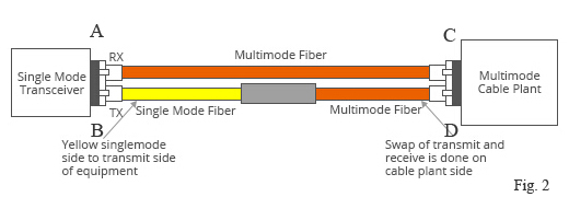
If your gigabit LX switch is equipped with SC or LC connectors, please be sure to connect the yellow leg (Singlemode) of the cable to the transmit side, and the orange leg (multimode) to the receive side of the equipment. It is imperative that this configuration be maintained on both ends. The swap of transmit and receive can only be done at the cable plant side. (see diagram below)

Notes
1. In some cases, customers might experience that a link would be operating properly over FDDI-grade, OM1 or OM2 fiber types without MCP. However please note there is no guarantee link will be operating properly over time, and the recommendation remains to use the MCP.
2. There is a risk associated to this type of nonstandard deployment without MCP, especially when the jumper cable is an FDDI-grade or OM1 type. In such case the power coupled directly into a 62.5-micron fiber could be as high as a few dBm and the adjacent receiver will be saturated. This can cause high bit error rate, link flaps, link down status and eventually irreversible damaged to the device.
3. Mode conditioning patch cords can only convert single-mode to multimode. If you want to convert multimode to single-mode, then a media converter will be required.
4. Another alternative for short reaches within the same location is to use a single-mode patch cable. There will be no saturation over single-mode fiber.
Specifications of Mode Conditioning Patch Cable (Notes:A B C and D,corresponding to A B C and D on Fig.2).
| Transmission Direction | Testing Wavelength | Insertion Loss |
| DuB | 850nm-1300nm | Max 0.30dB |
| BuD | 850nm-1300nm | Max 0.30dB |
| CuA | 850nm-1300nm | 15.0dB(50/125um) 18.0dB(62.5/125um) |
| AuC | 850nm-1300nm | Max 0.30dB |
| CuA | 1310nm-1550nm | 2.10dB(50/125um) 2.60dB(62.5/125um) |
| Return Loss | APC 60.0dB UPC 50.0dB | 35.0dB |
| Durability | 1000 mating | typical0.20dB |
| Operating Temperature | -40 to 85C | -40 to 185F |
Things to Know When Using Mode Conditioning Cables
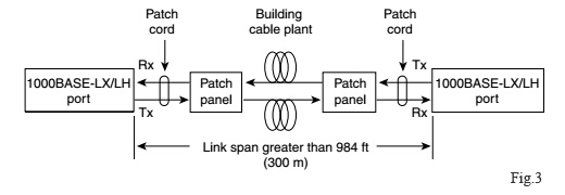
Mode conditioning patch cords are usually used in pairs. Which means that you will need a mode conditioning patch cord at each end to connect the equipment to the cable plant.
Generally, Mode Conditioning patch cords are required for link distances greater than 984 feet (300 meters).
Generally, Mode Conditioning patch cords are required for link distances greater than 984 feet (300 meters).

Detailed Picture(Offset)

